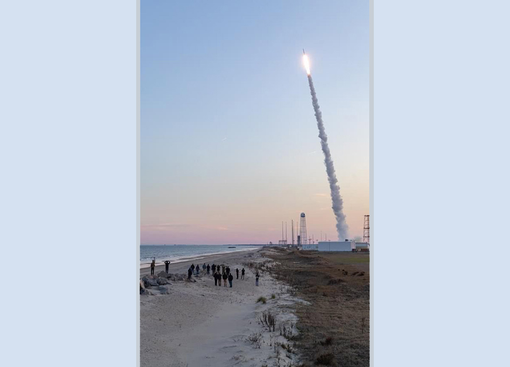
[Image above] In the cover article of the March 2020 issue of International Journal of Ceramic Engineering & Science, researchers in China report how wing shape affects thermal shock behavior of ultrahigh-temperature ceramics. Credit: IJCES
I traveled for business throughout most of my career to conferences, trade shows, training courses, sales meetings, and more. There truly is nothing like being together in person to foster greater understanding and cooperation. But business travel is time consuming and expensive, which brought about the era of the virtual meeting.
Due to COVID-19, most everyone reading this post will likely experience the virtual meeting firsthand. The technology makes virtual meetings simple and useful. But they are not all they are cracked up to be; they just can’t replace being able to read expressions and body language, and being able to hear those audible sounds of the emotional responses, in person.
Having grown up in the eras of the Concorde, Space Shuttle, and the Jetsons, I imagined by now we would travel across continents in just a few minutes and oceans in 1–2 hours to easily attend meetings in person. But while such transportation systems are not yet a reality for us, ceramics—specifically ultrahigh-temperature ceramics (UHTCs)—could help enable hypersonic vehicles.
When objects move quickly through air, the resulting friction causes them to heat up to very high temperatures. Space shuttles in the Space Shuttle Program were protected from this heat by low density ceramic tiles adhered to the outer surfaces. While this solution was mostly successful for the shuttle program, the bricks were large and relatively heavy, making them otherwise impractical for commercially viable aircraft, particularly for control surfaces.
UHTCs are promising for control surfaces, for example, the leading edges of wings. But one barrier that eludes ceramic scientists and engineers is resistance to thermal shock. Thermal shock occurs when temperatures change rapidly. The thermal expansion stresses from temperature gradients within low thermal conductivity ceramics can fracture them.
Thermal shock, much like fracture and strength, has components from both intrinsic material characteristics and extrinsic processing effects. While there are standard tests for thermal shock, such as ASTM C1171, C1525, and C484, they are most appropriate for comparing material properties or properties in narrowly defined use windows. However, the simple shapes of these tests cannot adequately reflect boundary conditions pertinent to the specific geometries needed for hypersonic flight.
Researchers at Nanjing Institute of Technology led by Anzhe Wang developed a method for testing how thermal shock affects geometries that model the sharp leading edge of airplane wings. Their open-access article, which is the cover article for the March 2020 issue of the International Journal of Ceramic Engineering & Science, is systematic analysis of four geometric parameters’ effects on failure temperature.
Before I discuss the results, the method itself intrigued me. The sample and holder are heated to the thermal shock test temperature. They are removed from the furnace and immediately sprayed with water, with the process being recorded in-situ. This process is very different from most shock tests, where samples are dropped into water. The figure below (Figure 2 from the article) shows three screen shots from the video recording.
After seeing this figure, I wondered what the full recording might show that the still images did not. To that end I asked the researchers to provide me access to a video, which they kindly posted here. (And you can see below.)
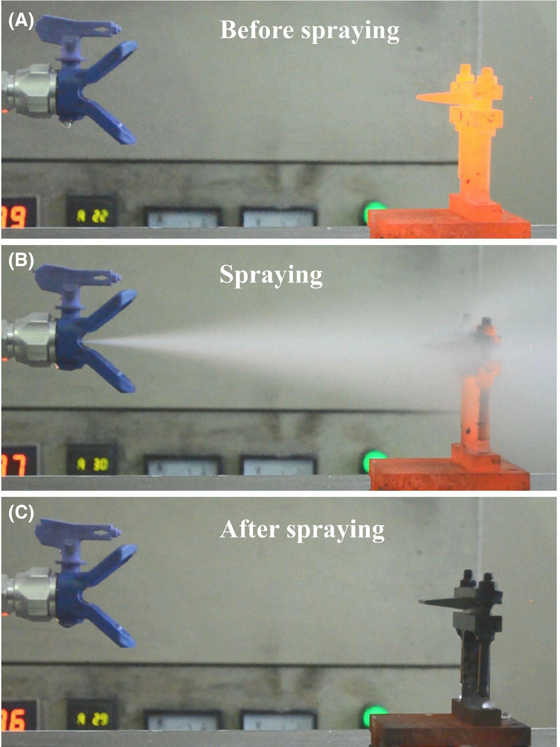
Typical screenshot for the video recording of the standard sample during thermal shock at the set temperature of 800°C. Credit: Wang et al., International Journal of Ceramic Engineering & Science

Credit: Vigour.Y Z, YouTube
The video, which is from some previously published work, does not disappoint. The first two segments are for the base material ZrB2-20 vol.%SiC and the second two are for 85% of the base material with 15% graphite. The base material cannot withstand thermal shock beyond 400°C—you can see the nose break away in the first segment and a chip breaking off in the second. The material with graphite appears to withstand thermal shock up to 800°C.
In the current study, the 85% (ZrB2-20%SiC) 15% graphite material was cut into several samples, each varying two of the four parameters: angle, length and thickness of the sharp edge, and tip radius. Of these parameters, angle and length of the sample had the greatest influence, with smaller angles and shorter samples having significantly reduced thermal shock resistance.
These results seem contradictory to me. Shorter samples, which failed at lower temperatures, have higher angles. Yet samples with lower angles also failed at low temperatures. Complicating the situation were little difference in failure temperature when changing thickness.
The researchers solved this conundrum through microscopy observations of crack propagation and finite element modeling.
The modeling uses thermal conductivity to determine internal temperature transients. Stresses build up due to differences in thermal expansion. The critical failure temperature is defined as the starting temperature at which internal stresses exceed the critical failure stresses.
The modeling showed substantially reduced critical failure temperatures (as a result of higher stresses) in both the small angle and short sample formats, whereas thickness had little influence on the behavior. So even though the results are not intuitive, the modeling demonstrates the internal temperature gradients and resulting stresses can lead to the observed results.
You can read details of the testing, analysis, and modeling at https://doi.org/10.1002/ces2.10041.
The open-access paper, published in International Journal of Ceramic Engineering & Science, is “Study on the effect of sample shapes on the thermal shock behavior of ZrB2‐SiC‐Graphite sharp leading edge” (DOI: 10.1002/ces2.10041).