
[Image above] Understanding damage caused by environmental silicate contamination to thermal and environmental barrier coatings is important to better protecting turbine blades made from ceramic matrix composites. Credit: Pro-Per Energy Services, Wikimedia (CC BY-SA 4.0)
Too much carbon dioxide in the atmosphere is one of the main factors causing the earth to grow rapidly warmer. But as illustrated in recent months with the greatly reduced use of transportation, the earth can heal if we can use our resources more wisely.
In the ideal world of the future, all hydrocarbon fuels will be replaced by natural energy sources, such as wind-generated electricity and solar-generated steam. Though we are moving in that direction, many technological barriers have yet to be overcome—meaning hydrocarbon fuels will continue to be used, especially in transportation and electricity generation. However, improving efficiency in passenger vehicles helped to reduce fuel consumption. We must continue to improve efficiency and extend technologies, especially for more powerful turbine-driven applications such as jet aircraft, large ocean-going vessels, and gas-fired electricity plants.
Raising turbine operating temperatures is one path to greater fuel efficiency. But target temperatures approaching 1,400°C present significant materials challenges. Specifically, the materials used in turbine blades, such as SiC-SiC ceramic matrix composites (CMCs), tend to oxidize and volatilize in the hot, humid gases.
The most common approach to protecting the CMCs is application of thermal and environmental barrier coatings (TBCs, EBCs). Two groups of TBCs and EBCs being tested are based on rare-earth silicates and aluminates.
As with any solution, new challenges arise. In the case of rare-earth silicates and aluminates, they react with other silicates that are deposited from the environment during operation. The reactions lead to new compositions with new crystal and glass structures (along with liquids) and different thermal expansion coefficients. Complicating the situation is the breadth of environmental silicates compositions, which arise from very fine particulates of sand, volcanic ash, and fly ash, among others.
Three recent papers co-authored by David Poerschke, assistant professor at the University of Minnesota and chair of ACerS Publications Committee, provide extensive insights into the many aspects of damage caused by environmental silicate contamination of TBCs and EBCs. While I cannot even begin to explain the breadth and depth of their experimentation, modeling, and analysis, I hope to spark enough interest for you to read, understand, and expand upon their excellent work.
Defining the problem
The figure below represents a degradation mechanism for TBCs and EBCs. While the turbine is in operation, deposits accumulate, liquify, and react with the coatings. Upon cooling, thermal expansion mismatch causes stresses, which are relieved by cracking. The still-liquid deposits flow into the cracks and penetrate the coatings via porosity and grain boundaries. Upon further cooling, thermal mismatch can lead to spallation, i.e., the ejection of fragments from a material due to impact or stress.
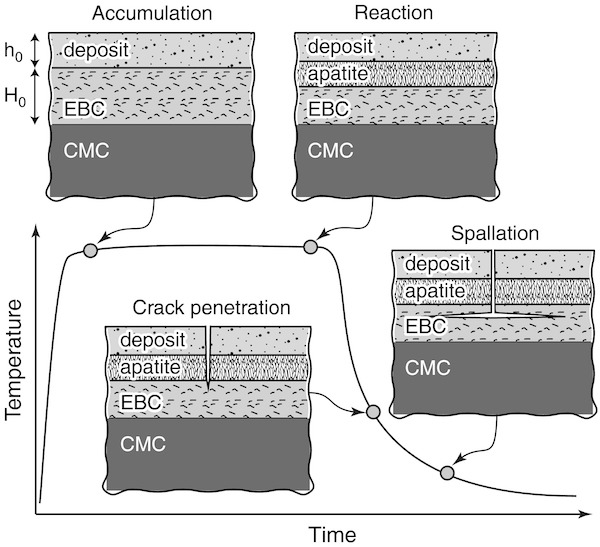
There are a number of methods for minimizing cracking, preventing deep penetration, or minimizing the thermal mismatch energy that leads to these effects. These methods include consuming the deposits while converting them to favorable materials, forming new phases that stop the reactions from occurring, and developing materials with low thermal expansion coefficients that place the TBC or EBC in compression upon cooling to stop crack growth.
To implement these methods requires data on material properties, phases, and structure, among others. And in the paper “A computational modeling framework for reaction and failure of environmental barrier coatings under silicate deposits,” the researchers create a model combining reaction, geometric, thermo-physical, and thermo-mechanical parameters to provide predictions of composition, thickness, thermal expansion, and fracture mechanics of the intermediate and end-of-cycle substrate/coating/deposit structure.
The chemical reactions considered in this paper are between yttrium disilicate and environmental contaminants, consisting of mixtures of calcium, magnesium, iron, aluminum, and silicon oxides (short-hand notation: CMFAS). Many deposit compositions and thicknesses are input into the sequence of models used in this study.
The results of this modeling and simulation study cover a wide range of behaviors. But two results that are consistent throughout the three papers being discussed are
- Calcium rich deposits tend to strongly increase degradation of the coatings, and
- Under reasonable conditions, the coatings can survive environmental deposits.
Understanding material properties through phase diagrams
Phase Equilibrium Diagrams (phase diagrams for short) are 2D representations of the interactions of composition, temperature, crystal structure, phase (solid, liquid, gas), pressure, and other physical properties of multicomponent chemical systems under equilibrium conditions.
Given the sheer number of parameters, there are a huge number of potential phase diagrams for any given system. So knowing what is being displayed is the first key to understanding the data.
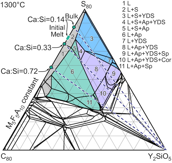
The article “Reactions of molten silicate deposits with yttrium monosilicate” shows a phase diagram for yttrium monosilicate and CMFAS deposits in various concentrations developed from equilibrium thermodynamic relationships. It is notable the yttrium monosilicate is not thermodynamically stable with the CMFAS deposits. In other words, they do not coexist but react to form apatites and disilicates.
It is also worth noting the equilibrium conditions of the phase diagram were not reached during the experimentation, indicating kinetic hindrance, and the formation of the garnet phase was witnessed, which was not predicted by the models used. The data in this paper confirm calcium has a strong influence on reactions, with further evidence showing that Ca:Si ratio of about 0.2 is a reaction boundary.
The article “Garnet stability in the Al–Ca–Mg–Si–Y–O system with implications for reactions between TBCs, EBCs, and silicate deposits” can be read as a master class for experimentally developing a series of phase diagrams for a multielement system. The premise being explored is compositional space, in which garnet formation is significant.
As mentioned above, reactions of silicates and aluminates with environmental silicates can create apatite phases that compromise the integrity of the coating. The previous paper showed garnet structures can form from the elements typically found in TBCs, EBCs, and CMFAS contaminants, though the thermodynamic models did not predict them. While it is hypothesized the garnet structure could be less destabilizing than the apatite structures, not much is known about the range of stability for garnets in this complex chemical system.
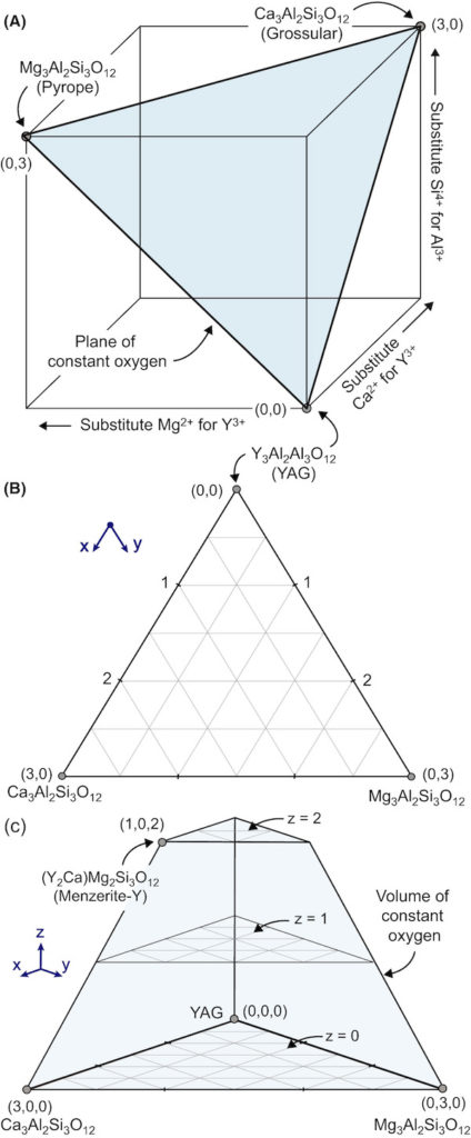
The researchers begin by defining the possible compositional space for garnets beginning with yttrium aluminum garnet (YAG), which has three possible cation sites. Two sites are occupied by aluminum and the third by yttrium. Given the sizes and charges of the environmental contaminant cations—Ca2+, Mg2+, and Si4+—there are specific limits to how these ions can substitute for Al3+ and Y3+. These limits lead to the following rules:
- One Ca2+ and one Si4+ must substitute for one Y3+ and one Al3+, respectively, to maintain oxygen balance.
- One Mg2+ and one Si4+ can substitute for one Y3+ and one Al3+ or two Al3+ because Mg2+ can occupy sites occupied by both Y3+ and Al3+. Calcium can only occupy the Y3+ site.
Rule 2 creates many limitations to the compositional space. For example, at most three calcium + magnesium ions can substitute into the unit cell because there are only three sites available for silicon. The researchers approached these limitations by controlling the compositions to “force” magnesium into either site and by creating a 3D compositional space. To understand the 3D space, the researchers show different “slices” of the space in two dimensions. (It is quite fascinating.)
The researchers formulated and reacted many compositions within the possible space and reported the phase (by XRD), microstructure (SEM), and quantitative composition results on 19 such formulations. Their conclusions are rich with information about garnet formation and limitations. A few conclusions that caught my eye include
- Garnet formation reduces melt (impurity) volume more than apatite per mole of yttrium consumed, though there are concerns about crystallization kinetics that need to be researched further.
- Only pure YAG created single phase garnet, but compositions with greater yttrium content had higher garnet stability.
- Magnesium preferentially substitutes for aluminum over yttrium and thus can form garnets with somewhat higher magnesium concentrations than can be formed for pure calcium garnets.
Phase diagrams are used quite differently in the first paper, i.e., “A computational modeling framework.” In addition to the phase/composition boundaries of the latter two papers, this paper uses phase diagrams to visualize physical properties as functions of composition and phase. For example, one series demonstrates the consumption of the coating and the corresponding amounts of apatite and silica and how the reactions differ depending on the composition of the deposit. Other series examine thermal expansion and glass transition temperatures.
In summary, thermal and environmental barrier coatings made from rare-earth silicates show great promise for enabling higher temperature, more efficient hydrocarbon-fueled turbine engines. Yet there still is much to learn. Based on the three articles presented here, future work should include exploring ways to mitigate calcium contamination and studies of the kinetics of the reactions with the environmental contaminants.
Read more about the construction and interpretation of phase diagrams by downloading General Discussions of Phase Diagrams by F.P. Hall, H. Insley, E.M. Levin, H.F. McMurdie and C.R. Robbins from the ceramics.org website. More information about the range of phase diagrams available through the NIST/ACerS Phase Equilibrium Diagram database can be found at https://ceramics.org/publications-resources/phase-equilibrium-diagrams.
The first paper, published in Journal of the American Ceramic Society, is “A computational modeling framework for reaction and failure of environmental barrier coatings under silicate deposits” (DOI: 10.1111/jace.17187).
The second paper, published in Journal of the American Ceramic Society, is “Reactions of molten silicate deposits with yttrium monosilicate” (DOI: 10.1111/jace.16972).
The third paper, published in Journal of the American Ceramic Society, is “Garnet stability in the Al–Ca–Mg–Si–Y–O system with implications for reactions between TBCs, EBCs, and silicate deposits” (DOI: 10.1111/jace.17176).